Explore expert articles, technical guides, application case studies, and engineering updates from Menzel Motors.
A rolling mill’s drive system shapes more than motor speed. It influences strip thickness, surface quality, energy use, and unplanned downtime. For global buyers, choosing among the 7 Best Steel Rolling Mill Drives means looking beyond a catalogue rating. The right choice depends on the mill type, required torque, speed range, duty cycle, and operating environment. Small details matter.
John G. Lenard, a recognized author on metal forming, offers a useful perspective through his published work: rolling performance must be understood in relation to the process, not as an isolated machine specification. This is a paraphrase, not a verbatim quotation. It points buyers toward practical questions: Can the drive handle repeated acceleration? Does its control system maintain stable speed under changing loads? Are cooling, maintenance access, and spare parts suitable for the plant’s location?
This guide compares drive options through those real operating demands. It considers control precision, reliability, integration, energy performance, and support availability. A drive that looks efficient on paper may disappoint if commissioning is difficult or replacement components take weeks to arrive. That risk deserves attention. Specifications also cannot replace a site assessment; mill configuration and production goals vary. Use the comparisons as a starting point, then confirm ratings and compatibility with qualified suppliers and plant engineers.
A rolling mill drive converts electrical power into controlled roll motion. Its task is not simply to spin the rolls. It must provide enough torque to bite the steel, maintain the required speed, and respond when the material pushes back. During a pass, strip thickness, temperature, and rolling force can change. The drive must handle these shifts without creating unstable speed or excessive mechanical stress.
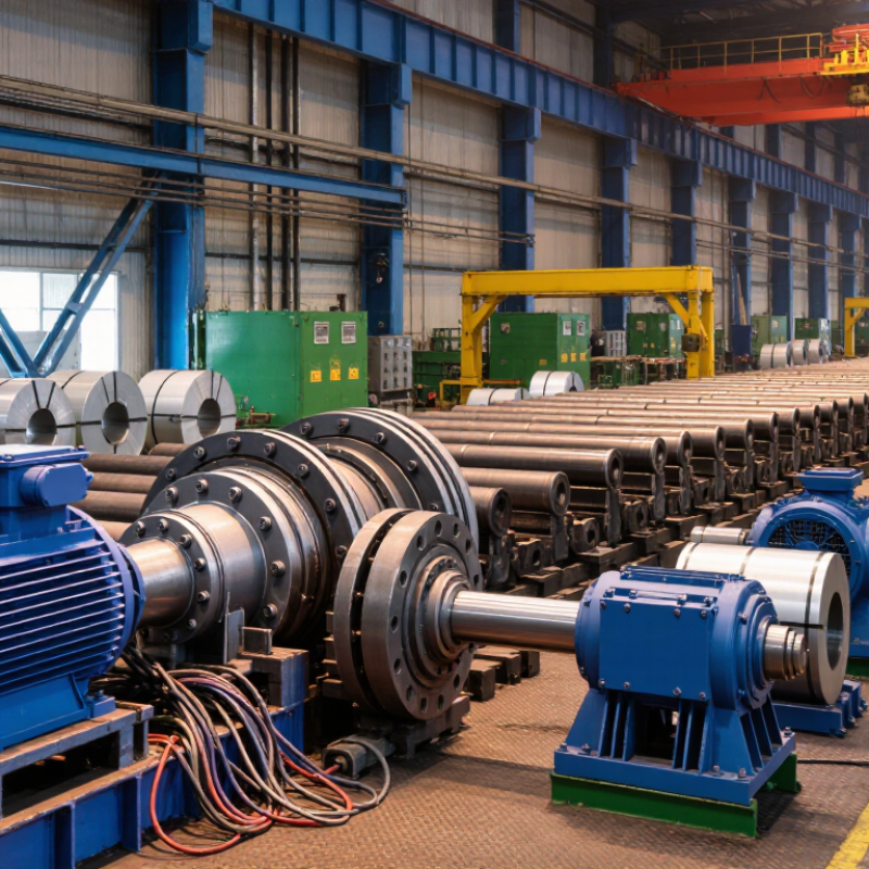
In many systems, a motor works with a power converter, gearbox, and coupling. The converter adjusts motor speed and torque by controlling electrical supply. The gearbox matches motor speed to the rolls, while the coupling transfers torque and helps accommodate small alignment differences. Sensors can report speed, motor current, or roll position to a control system. That feedback helps operators keep the process steady.
Small changes matter.
Drive selection depends on mill layout, required speed range, torque demand, and duty cycle. A rough sizing calculation may overlook repeated acceleration or sudden load changes.
That is worth checking.
Engineers should review operating data, cooling needs, and mechanical limits together, rather than treating motor power as the only deciding figure. Even a well-designed drive needs inspection; loose connections, worn couplings, or poor cooling can affect performance over time.
Modern rolling mills need drives that deliver high torque at low speeds and maintain stable control as the load changes. During a heavy pass, a drive may face a sudden torque rise; during a thinner pass, it must respond smoothly without creating speed swings. Specify the required speed range, overload duration, and stopping behavior with the mill’s actual process data. Guesswork here gets expensive.
Protection matters as much as power. Motors and drive cabinets must suit the mill’s heat, dust, vibration, and cooling conditions. Feedback devices can help regulate roll speed and coordinate sections, while suitable braking arrangements can manage deceleration and, where the system supports it, return energy. Check that alarms, isolation, and maintenance access are practical for operators. A technically capable drive is not automatically an easy one to service.
Tips: Ask suppliers for documented torque curves, thermal limits, and response data—not just rated power. Review cable routes and cabinet cooling before installation. Leave room for commissioning adjustments; real mill behavior can differ from clean design assumptions. Even a good specification may need revision after the first production runs.
Steel rolling mills need high starting torque, stable speed, and control under changing loads. Seven drive options suit different mill layouts: AC induction motors with variable-frequency drives, DC motor drives, synchronous motor drives, helical gear drives, planetary gear drives, direct-drive torque motors, and sectional drive systems. Some are motor types; others describe transmission or control arrangements, so they can be combined. That distinction matters.
Tips: Compare torque across the full speed range, not just the motor’s rated power. Check reversing duty, roll diameter, gearbox service factor, cooling, and access for maintenance. Ask suppliers to show load profiles and test data. Small omissions can become costly.
For a reversing stand, four-quadrant regenerative control may return braking energy and manage frequent direction changes. A direct-drive arrangement can remove gearbox stages, but its size and purchase cost may not suit every installation.
Planetary gearing offers a compact package for high torque; verify lubrication and inspection access. Sectional drives help coordinate multiple stands, though tuning and commissioning require care.
Request references for similar mill duties, plus clear limits for overload, temperature, and expected service life. A clean specification still cannot predict every shock load, so leave room for engineering review.
For global buyers, a rolling mill drive is not judged by peak torque alone. It must hold speed through changing billet loads, frequent starts, and brief interruptions. Direct-drive systems can reduce mechanical losses and coupling wear, while geared systems may offer practical torque control and familiar servicing. Compare rated power with the mill’s actual duty cycle, not a best-case figure. That detail matters.
Efficiency depends on more than motor ratings. Check inverter performance at partial load, cooling demand, and braking energy during deceleration. Ask for data from comparable rolling stands, including speed variation and operating temperatures. Maintenance needs differ: gearboxes require oil checks and alignment inspections; electrical drives need clean cabinets, secure terminals, and working cooling fans. Dust gets everywhere. Planned downtime is usually easier to manage than an unexpected bearing failure, though estimates can be imperfect.
Tips: Request a maintenance schedule, spare-parts list, and service response times before comparing prices. Check access around motors and gearboxes; technicians need room for tools, not just a tidy drawing. Track vibration and winding temperature after commissioning. If energy figures seem unusually precise, ask how they were measured. Small omissions happen, even in careful evaluations.
Drive selection should begin with the mill’s duty cycle, not a catalogue rating. World Steel Association data puts 2024 global crude steel production at about 1.88 billion tonnes, across plants with very different schedules and product mixes. That scale matters. A roughing stand needs strong low-speed torque and short overload capacity. A finishing stand often needs fast, precise speed control to hold strip thickness and surface quality. Reversing mills also require four-quadrant operation, while tandem lines depend on closely coordinated stand speeds. Brief overloads count.
Match the drive to the actual torque-speed curve, roll inertia, starts per hour, and cooling conditions. Then check converter harmonics and the time required to recover after a cobble or planned stop. The International Energy Agency’s 2020 Iron and Steel Technology Roadmap estimates the sector produced about 2.6 gigatonnes of CO₂ in 2019, roughly 7% of global energy-system emissions. Efficient operation deserves attention, but efficiency figures alone can mislead. A lower-loss drive may not suit a mill with frequent high-torque reversals. Ask operators to compare logged load profiles with supplier calculations and maintenance records. Measure real duty. It is easy to overlook.
| Drive Configuration | Best-Fit Mill Type | Production Goals | Key Selection Factors | Trade-Offs to Consider |
|---|---|---|---|---|
| Reversible main drive with regenerative AC variable-frequency control | Reversing plate, Steckel, and other reversing mills | Frequent forward-and-reverse passes, controlled acceleration, and reduced energy loss during braking | Check required torque over the full speed range, reversal frequency, motor cooling at low speeds, and the plant’s regenerative-power requirements. | Regenerative operation can return braking energy to the electrical system, but adds system and engineering requirements. Confirm that the supply network and protection design support it. |
| Individually controlled AC stand drives | Continuous and tandem rolling mills | Coordinated operation across several stands and stable control of strip speed and interstand tension | Assess stand-to-stand speed coordination, response to load changes, encoder needs, communication with the line control system, and commissioning support. | Each stand can be controlled independently, but the complete line requires careful drive coordination and tuning. |
| High-power AC drive with induction or synchronous motor | Hot-strip finishing stands and other high-load mill stands | Reliable operation under demanding rolling loads and the required production speed | Compare motor torque and power across the operating range, overload capability, cooling arrangement, available installation space, and maintenance access. | The appropriate motor type depends on the duty and plant design; do not select on rated power alone. Review the motor and drive as a matched system. |
| Four-quadrant AC vector-controlled main drive | Cold rolling mills, including reversing applications | Precise speed and torque control during acceleration, deceleration, and changes in rolling conditions | Consider speed accuracy, low-speed torque, dynamic response, regenerative braking needs, and integration with thickness and tension control. | Performance depends on correct motor data, feedback configuration, and system tuning. Verify that the specified control method suits the process requirements. |
| Gearbox-coupled stand drive | Bar, rod, and section mills with separate driven stands | Matching stand speed to roll requirements while providing a practical mechanical connection to the rolls | Check gear ratio, torque rating, duty cycle, lubrication, alignment, gear condition, and the effects of backlash on process control. | Gearboxes can adapt motor speed to roll speed, but introduce mechanical components that need inspection and maintenance. |
| Four-quadrant tension-control drive | Hot- or cold-strip coilers and uncoilers | Maintaining controlled strip tension as coil diameter and line speed change | Specify the tension range, speed range, coil inertia, diameter measurement method, braking duty, and coordination with the mill line. | Control settings must account for changing coil diameter and inertia. Validate the complete tension-control strategy under expected operating conditions. |
| Modern DC motor drive for an existing DC installation | Legacy mills designed around DC motors and DC control equipment | Maintaining an established drive system or planning a phased modernization | Review the condition and availability of the motor, converter, spare parts, control interfaces, and the cost and scope of any AC retrofit. | DC technology can suit an existing installation, but replacement-part availability and long-term maintenance should be evaluated before extending the system’s service life. |

Common options include AC induction motors with variable-frequency drives, DC drives, synchronous motors, helical and planetary gear drives, direct-drive torque motors, and sectional systems. Some describe motor types; others describe transmission or control arrangements, so they can be combined.
Compare torque across the full speed range, not just rated power. Check the mill’s duty cycle, billet loads, starts, interruptions, and speed stability.
Four-quadrant regenerative control can manage frequent direction changes and return braking energy. Confirm that its performance suits the stand’s actual operating profile.
Direct drives can remove gearbox stages, reducing some mechanical losses and coupling wear. They may also require more space and higher initial cost.
Planetary gearing can provide high torque in a compact package. Check lubrication requirements and whether technicians can reach inspection points.
They coordinate multiple stands and can support controlled operation across the line. Tuning and commissioning need care; one setup may not fit every mill.
Ask for a maintenance schedule, spare-parts list, and service response times. Check access around motors and gearboxes so technicians have room to work.
Request load profiles and test data from comparable rolling stands, including temperature and speed variation. Ask how efficiency figures were measured. Estimates can still miss shock loads.
Steel rolling mill drives are essential to controlling the speed, torque, and stability of rolling processes. They coordinate motor output with mill loads, helping maintain consistent product dimensions and reliable operation. Modern systems must respond precisely to changing production demands while balancing energy efficiency, durability, safety, and ease of maintenance. Different drive options can serve different stages and configurations of a mill, so buyers should compare their operating performance, control capabilities, service requirements, and suitability for demanding production environments.
Choosing among the seven leading types of Steel rolling mill drives begins with understanding the mill’s design and production goals. Consider the material being processed, required output, expected operating conditions, and the level of control needed. A careful comparison of efficiency, reliability, maintenance needs, and lifecycle costs can help buyers select a drive that supports steady production and long-term performance without over-specifying the system.